case study for cctv installers
case study for cctv sales engineers
cctv lens calculator
Online CCTV Bandwidth and Storage Space Calculator
IPICA ratings
  Youtube Channel Linkedin Twitter  
 

Pixel Density, PPM and PPF in Video Surveillance

We are surrounded by high detail images every day. Our cellphones can capture images at 10 megapixels or more, common televisions can stream 4K content, and multi-megapixel CCTV cameras are part of almost every system installed today. These factors can lead some users to expect more detail from their CCTV systems than the system is actually capable of.

In order for our systems to meet the expectations of the users we need to first know what level of detail the user requires, often referred to as “Pixel Density”. As you might imagine, a 4MP (mega-pixel) image sensor looking at an area the size of a postage stamp would capture very high detail. That same sensor mounted high above a large parking lot, looking at an area large enough to hold 500 vehicles would capture very little detail. Calculating which sensor and lens combination is required to deliver the right level of detail, or pixel density, in a given area is the job of the qualified system designer.

PPM and PPF in security industry

Sometimes resolution is confused with pixel density, particularly by users not familiar with CCTV concepts. Resolution describes the total number of pixels in an image, or the total number of pixels of an image sensor. It does not address how many of those pixels are focused on a specific object or area of the image, which is the pixel density.

Specific pixel density levels in CCTV images are referred to as PPM (pixels per meter) or PPF (pixels per foot), depending on the region where the system is being specified. These terms refer to how many pixels of an image sensor would be spread across a 1 meter or 1 foot horizontal measurement in a scene,. You may also come across PPI (pixels per inch) or PPCM (pixels per centimeter) when dealing with specifications for monitors or printers, where the area of the pixels, such as a piece of paper, is much smaller than the area viewed by a typical CCTV camera.

One of the constraints of extracting image detail from a live or recorded video image is that the user is limited by the fact that any detail must be present in the original image.

The image below depicts varying degrees of pixelization. A better method of defining image detail is by pixel density on a target (pixels per foot or pixels per meter).

Pixel density is obtained by dividing the camera horizontal resolution by field of view width. 

CCTV system designers tend to use the following categories to describe pixel density levels in an image, in order from most to least detailed:

  • Identification
  • Recognition
  • Observation
  • Detection
  • Monitoring

The following image shows representative examples of each level:

Pixel Density on target for different operator tasks. PPM, PPF based on EN 62676-4

Figure 1. Image detail quantified in pixels per meter or pixels per foot (PPM/PPF numbers based on mm per pixel specified by IEC/European Standard EN 62676-4: 2015)

The higher the pixel density, the higher the quality of the picture. With higher pixel density, you can distinguish smaller details.

It is important to note that final image quality is dependent on a number of factors, including available lighting, camera focus, shutter speed, codec compression, and other criteria. Still, without calculating appropriate detail levels for the common scenario we have no hope of delivering a system that meets customer needs.

Pixel Density Calculations

As an example, let’s take a common 1080p camera sensor, which is 1920 pixels wide, and 1080 pixels tall. If we take an area of the image that is approximately 6 meters, or 20 feet, wide we would calculate: 1920px / 6M = 320 PPM, oe 1920px / 20FT = 96 PPF, which would yield a very high detail image, assuming sufficient lighting, focus, etc. If we use the same camera to cover an area 60M/200FT wide, we would have 32PPM / 2PPF, which would only enable us to know that there is general activity in the area, but we would not be able to see specific details about the scene or objects.

Pixel density calculations do not take into account sensor size, or lens parameters, they are a factor of the resolution of the sensor, and the width of the scene. In order to calculate the appropriate lens value for a given sensor resolution and size to meet pixel density requirements is commonly done with design software, due to the vast number of possibilities available in the market today.

By utilizing software such as our design tool, the system designer can quickly determine the appropriate sensor, lens, and camera position to achieve the desired level of detail for a given camera location. Take for example the following example, based on a Hanwha 1080p dome camera:

pixel desnity calculation using jvsg tool

Both cameras are configured to offer ~60PPF for a target at the leading edge of the red Identification zone. However Camera 2 is placed much closer to the target, as it is using a smaller lens (6mm) vs. the 10mm lens of Camera 1. Both cameras would provide similar levels of detail in that area.

You may also notice that the depth of the various detail zones varies with the lens selected. Larger lenses will provide higher details over longer portions of the field of view than smaller lenses for a given sensor resolution and size. However, you would need more cameras to cover a given area, and the blind spot in front of the camera will be larger with the longer lens camera options. By using our modeling software, designers can quickly visualize and evaluate these trade-offs to find the best camera, sensor, lens, and placement combinations.

The JVSG design tools will auto-calculate pixel density levels throughout the scene and automatically color-code the camera’s view accordingly. As you are likely already aware, the further the subject is from the camera, the lower the pixel density. Doing these calculations can ensure we can capture adequate detail at expected target locations within the scene.

By default, the IP Video System Design Tool shows camera zones according to international / European Union standard IEC/EN 62676-4: 2015 (and older EN 50-132-7). Part 4 of that standard covers the different operator’s tasks, including identification, recognition, observation, detection, and monitoring.


Because a calculated PPM/PPF value only exists at a specific point in the image, these values are often expressed rounded to the nearest 10’s or 5’s value, eg: 40PPF, 125PPM, 90PPM, etc. In some cases they may be used to indicate a best case scenario, representing a location closest to the camera, or in other cases they may be used in a worst case scenario, representing a location furthest from the camera, which would indicate that subjects closer to the camera would have even more detail. It is important to understand customer expectations for detail levels, and to explain accordingly what to expect throughout the field of view of the camera. The JVSG Design Tool can auto calculate these values for any portion of the image, and allows you to place multiple sample targets, with the software showing a rendering of what an average face or license plate would look like in that portion of the image:

PPF PPM indicator in JVSG Desgin Tool
By understanding pixel density you can better convert customer requests, such as “I’d like to capture license plates at this location” or “I’d like to be able to tell if my workers are wearing hard hats” to specific design criteria, such as camera location, resolution, and lens parameters to deliver a system that meets their expectations without costly change orders or guesswork.

DORI Zones

DORI stands for Detection, Observation, Recognition, Identification. You can use IP Video System Design Tool or online Pixel Density Calculator to see DORI zones.

Identification: The first type of camera zone is the identification zone. In the program, this is marked in red. In this area, you can positively identify a person beyond reasonable doubt. Here we have sufficient picture quality and detail to identify an individual. The EU standard defines the identification area as “more than 4mm at the target distance per pixel”. If we covert 4mm per pixels to pixel density (1000mm divide by 4 mm per pixel),  the result is 250 pixels per meter (PPM) or about 76 pixels per foot (PPF).

Recognition: The second zone is recognition, marked in yellow. In this area, the security operator will be able to recognize a person known to them. Viewers can verify with a high degree of certainty whether or not an individual shown is the same as someone they have seen before. In this area, the pixel density is not less than 125 PPM (38 PPF) or 8mm per pixel. Also in this area, it is possible to recognize license plates manually, but the camera resolution maybe not sufficient for Automatic number plate recognition (ANPR) systems.

Observation: Next we have the observation zone (green). In this area, some characteristic details of the individual, such as distinctive clothing, can be seen. The pixel density is 62 pixels per meter or about 19 PPF (16mm per pixel by EN 62676-4)

Detection: Next is the detection zone (light green). In this area, where the operator will be able to detect a human presence: 25 PPM or 8 PPF (40mm per pixel).

Monitoring: The monitoring zone (blue) is used to monitor or perform crowd control. 12PPM / 4 PPF/ 80mm per pixel.

There is also a special kind of zone called Inspection or Strong Identification: 1000 PPM or 303 PPF  (or 1mm per pixel by EN 62676-4), marked as purple in the program.

Figure 2. shown above depicts the difference in image detail at various levels from 4 pixels per foot (12 pixels per meter) to 76 pixels per foot (250 pixels per meter).


It can be a time-consuming task to find available camera resolution and lens combinations for the required pixel density if done manually.

This task is automated with the IP Video System Design Tool, which has an integrated pixel density calculator that calculates the pixels per foot or per meter and illustrates the detail level with color-coded (red, yellow, green, blue) areas. Apart from IP Video System Design Tool you can also use our online PPF PPM Calculator here.

Part 2: Pixel density, camera zones, identification, recognition, detection and EN 62676-4: 2015


Pixel density zones on a site plan

Figure 3. Camera Coverage illustration

There are other standards that are supported by the IP Video System Design Tool.

See also: Pixel Density Calculator

Department of Homeland Security 2013 (DHS 2013) Recommendations

Department of Homeland Security 2013 (DHS 2013) published its own recommendations for pixels per foot for different video surveillance functions in the Digital Video Quality Handbook (pages 27-28).

1. Observation: 20 PPF
2. Forensic review: 40 PPF
3. Recognition: 80 PPF

DHS pixel per foot recommendation for video surveillance functions: observation 20ppf, forensic-review 40ppf, recognition 80ppf

Observation, Forensic review and Recognition PPF by DHS 2013 in JVSG tool

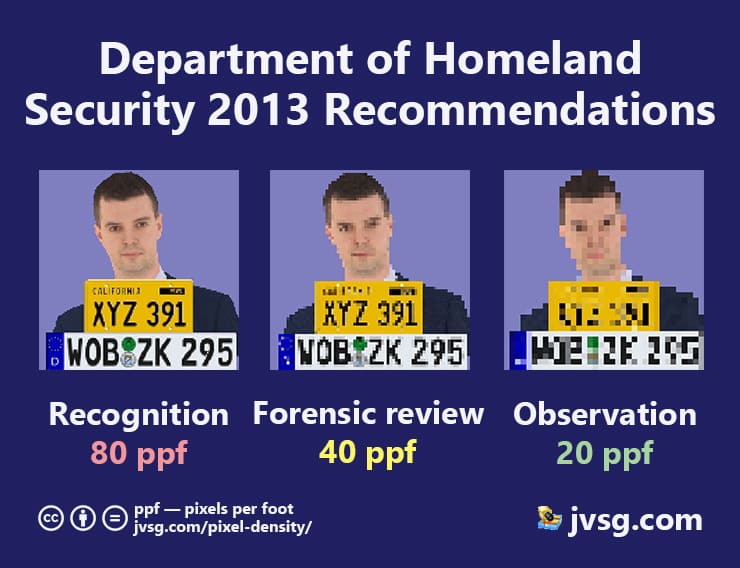
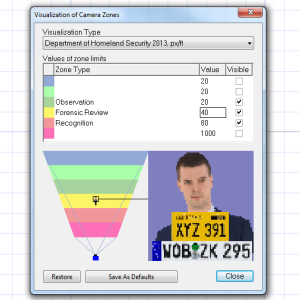
We can see that the DHS Observation: 20 pixel per foot zone is close to EU Observation: 19 pixel per foot zone (or 16mm per pixel by EN62676-4), but 80 PPF of the DHS Recognition zone is closer to the European EN Identification zone.


Proposed French standard*

The newly-proposed French standard discusses different pixel density and PPM numbers for Detection/Observation/Recognition/Identification (DORI) tasks.

You can adjust PPM values for the new proposed French stanard

1. Detection: 30 PPM
2. Recognition: 100 PPM
3. License Plate Reading: 200 PPM
4. Identification: 400 PPM

*Please note that this is a draft. Please do not cite or distribute.

Australian Corrigendum* for IEC 62676-4

Here are pixel density values proposed by Australian corrigendum to the international standard IEC 62676.

1. Monitoring: 17 ppm
2. Detection: 35 ppm
3. Observation: 88 ppm
4. Recognition: 175 ppm
5. Identification: 375 ppm
6. Strong Identification: 1400 ppm

These numbers are supported by JVSG Design Tool version 2022 and newer.
You can also specify your own PPF/PPM values in the Camera Visualization Window (Settings menu item) of the IP Video System Design Tool.


Site Plan, Floor Plan, and Obstacles

A site/floor plan can be loaded from a file or created in the JVSG Design Tool software using objects such as walls, boxes, doors, windows, fences or stairs. The user can add test people, cars, trees, furniture, and other test objects.
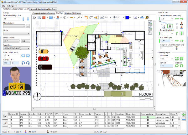
Pixel density DORI zones on a floor plan

By positioning all of these objects and viewing your site plan, you can decide where to locate and how to position your cameras.


On the next 3D View tab of the IP Video System Design Tool, you will see the Camera 3D View enlarged.

Using your mouse, you can adjust the camera direction and position.


Figure 4. Computer simulation of image size on screen

Conclusion

PPM and PPF are popular metrics in the video surveillance industry.

The IP Video System Design Tool software performs pixel density calculations and allows the use of customer-provided site plan drawings (PDF files, JPEG/PNG images, and AutoCAD DWG drawings) to find optimal camera locations, camera resolution,field of view and lens focal length.

We can also create a virtual working space with objects such as walls, people, cars and trees that make sense to our customers. Thus, we can show clients a schematic layout which is very similar to the real world as they evaluate whether the proposal is acceptable.

A trial version of IP Video System Design Tool can be downloaded from jvsg.com.

download now 300 MB ZIP

Video tutorials are here and here.  An youtube visual explanation of EN64676 (EN50132-7) operator tasks is here.

on 2nd of September 2022

IP Rating and IK Rating

IK & IP Ingress Protection Rating

Content:
IP Rating
IK Rating
NEMA Ratings

What are IK and IP?

In video surveillance, the camera ruggedness rating is indicated by an alphanumeric index – IKxx and IPxx.

IKxx – camera resistance to mechanical damage.

IPxx – protection against the effects of small particles, dust and moisture.

IP Rating

What is IP Rating

Rating IP is an international standard according to IEC 60529 indicating how the camera is protected against moisture and dust entering the housing. The IP rating can be used to determine the level of weather resistance that the camera can demonstrate, whether it will be able to operate in snowfall or other weather conditions that could potentially affect the quality of the images the camera receives and its uninterrupted operation.

The level of protection of the video camera is shown by two numerals after “IP”, for example, IP67, the first numeral “6″ – indicates the resistance of the camera to dust, and the second “7″ – for protection against moisture.

Rating IP

The camera’s resistance to dust (first numeral, after IP):

0 – no protection

1 – camera protection from solid objects larger than 5 cm

2 – protection from solid objects larger than 1.2 cm

3 – protection from solid objects larger than 0.25 cm

4 – protection from solid objects larger than 0.1 cm

5 – dustproof camera, a small amount of dust can get into the camera body, however, it does not affect the operation of the camera

6 – dust-tight chamber, fully protected against dust and deposits

The camera’s resistance to moisture entering the housing (second numeral):

0 – no protection

1 – protection from vertically falling drops of water that do not affect the operation of the camera

2 – protection from spraying water at an angle of up to 15° from horizontal

3 – protection from spraying water at an angle of up to 60° from horizontal

4 – protection from splashing, spraying water on all sides (slight penetration of moisture is possible)

5 – protection from a weak water jet (possible insignificant penetration of moisture inside the housing)

6 – protection from a strong water jet (slight penetration of moisture is allowed)

7 – protection from submerging the camera in water for a short time (up to 30 minutes) to a depth of up to 1 meter

8 – protection from the immersion of the camera in water for up to 30 minutes to a depth of more than 1 meter

9 – protection from prolonged immersion in high temperature pressurized water

Try our free Security Camera Lens Calculator:
https://www.jvsg.com/calculators/cctv-lens-calculator/

IP Rating Chart

IP rating camera dust resistance moisture protection
IP00 no dust protection no protection against moisture
IP01 no dust protection condensation protection
IP02 no dust protection protection against splashing water at an angle of up to 15° from vertical
IP03 no dust protection protection against splashing water at an angle of up to 60° from vertical
IP04 no dust protection protection against water spray from all sides
IP05 no dust protection protection against weak water jets
IP06 no dust protection protection against strong water jets
IP07 no dust protection protection from immersion to a depth of 1 meter for up to 30 minutes
IP08 no dust protection protection from immersion to a depth of more than 1 meter for up to 30 minutes
IP10 protection from solid objects over 5 cm no protection against moisture
IP11 protection from solid objects larger than 5 cm condensation protection
IP12 protection from solid objects larger than 5 cm protection against splashing water at an angle of up to 15° from vertical
IP13 protection from solid objects larger than 5 cm protection against splashing water at an angle of up to 60° from vertical
IP14 protection from solid objects larger than 5 cm protection against water spray from all sides
IP15 protection from solid objects larger than 5 cm protection against weak water jets
IP16 protection from solid objects larger than 5 cm protection against strong water jets
IP17 protection from solid objects larger than 5 cm protection from immersion to a depth of 1 meter for up to 30 minutes
IP18 protection from solid objects larger than 5 cm protection from immersion to a depth of more than 1 meter for up to 30 minutes
IP20 protection from solid objects larger than 1.2 cm no protection against moisture
IP21 protection from solid objects larger than 1.2 cm condensation protection
IP22 protection from solid objects larger than 1.2 cm protection against splashing water at an angle of up to 15° from vertical
IP23 protection from solid objects larger than 1.2 cm protection against splashing water at an angle of up to 60° from vertical
IP24 protection from solid objects larger than 1.2 cm protection against water spray from all sides
IP25 protection from solid objects larger than 1.2 cm protection against weak water jets
IP26 protection from solid objects larger than 1.2 cm protection against strong water jets
IP27 protection from solid objects larger than 1.2 cm protection from immersion to a depth of 1 meter for up to 30 minutes
IP28 protection from solid objects larger than 1.2 cm protection from immersion to a depth of more than 1 meter for up to 30 minutes
IP3X protection from solid objects larger than 0.25 cm not tested
IP30 protection from solid objects larger than 0.25 cm no protection against moisture
IP31 protection from solid objects larger than 0.25 cm condensation protection
IP32 protection from solid objects larger than 0.25 cm protection against splashing water at an angle of up to 15° from vertical
IP33 protection from solid objects larger than 0.25 cm protection against splashing water at an angle of up to 60° from vertical
IP34 protection from solid objects larger than 0.25 cm protection against water spray from all sides
IP35 protection from solid objects larger than 0.25 cm protection against weak water jets
IP36 protection from solid objects larger than 0.25 cm protection against strong water jets
IP37 protection from solid objects larger than 0.25 cm protection from immersion to a depth of 1 meter for up to 30 minutes
IP38 protection from solid objects larger than 0.25 cm protection from immersion to a depth of more than 1 meter for up to 30 minutes
IP4X protection from solid objects larger than 0.1 cm not tested
IP40 protection from solid objects larger than 0.1 cm no protection against moisture
IP41 protection from solid objects larger than 0.1 cm condensation protection
IP42 protection from solid objects larger than 0.1 cm protection against splashing water at an angle of up to 15° from vertical
IP43 protection from solid objects larger than 0.1 cm protection against splashing water at an angle of up to 60° from vertical
IP44 protection from solid objects larger than 0.1 cm protection against water spray from all sides
IP45 protection from solid objects larger than 0.1 cm protection against weak water jets
IP46 protection from solid objects larger than 0.1 cm protection against strong water jets
IP47 protection from solid objects larger than 0.1 cm protection from immersion to a depth of 1 meter for up to 30 minutes
IP48 protection from solid objects larger than 0.1 cm protection from immersion to a depth of more than 1 meter for up to 30 minutes
IP50 protection against limited dust penetration no protection against moisture
IP51 protection against limited dust penetration condensation protection
IP52 protection against limited dust penetration protection against splashing water at an angle of up to 15° from vertical
IP53 protection against limited dust penetration protection against splashing water at an angle of up to 60° from vertical
IP54 protection against limited dust penetration protection against water spray from all sides
IP55 protection against limited dust penetration protection against weak water jets
IP56 protection against limited dust penetration protection against strong water jets
IP57 protection against limited dust penetration protection from immersion to a depth of 1 meter for up to 30 minutes
IP58 protection against limited dust penetration protection from immersion to a depth of more than 1 meter for up to 30 minutes
IP5K9K dust protected withstands high pressure wash
IP60 protection against any dust ingress no protection against moisture
IP61 protection against any dust ingress condensation protection
IP62 protection against any dust ingress protection against splashing water at an angle of up to 15° from vertical
IP63 protection against any dust ingress protection against splashing water at an angle of up to 60° from vertical
IP64 protection against any dust ingress protection against water spray from all sides
IP65 protection against any dust ingress protection against weak water jets
IP66 protection against any dust ingress protection against strong water jets
IP67 protection against any dust ingress protection from immersion to a depth of 1 meter for up to 30 minutes
IP68 protection against any dust ingress protection from immersion to a depth of more than 1 meter for up to 30 minutes
IP69 protection against any dust ingress protection against prolonged immersion in high-pressure, high-temperature water
IP69K protection against any dust ingress protected against close-range high-pressure, high-temperature spray downs
IP6K9K protection against any dust ingress protected against high pressure/steam jet cleaning

IP44

Cameras with less than IP44 protection are cameras designed for indoor use only.

IP65

Cameras with a rating of between IP44 and IP65 are cameras that require additional protection when installed outdoors.

IP66, IP67

IP66 and IP67 rated cameras are outdoor cameras that can work in all weather conditions, including heavy precipitation and wind, without additional protection.

IP68

IP68 rated cameras are dust-proof and are capable of being completely immersed in water for up to 30 minutes.

IK Rating

What is IK protection?

IK ratings are an international standard as defined in IEC 62262 which describe the ability of a camera structure to withstand various types of mechanical damage. The Rating IK indicates how rugged the camera housing is and the level of protection against mechanical impacts it can guarantee.

The protection level of the camera is indicated by two numerals after the letter designation, the cameras can have a protection level from 00 to 10 (the exposure level is measured in Joule). The meaning of the ratings are summarized below:

Up to IK05 – the camera housing can withstand an impact of up to 1 J

IK06-IK07 – the camera can withstand an object weighing up to 500 grams falling from a low height

IK08 – the camera can withstand an impact of up to 5 J (equivalent to a fall from a height of an object weighing more than 1500 grams)

IK10

IK09-IK10 rated cameras are high-strength/anti-vandal-resistant cameras, withstanding an impact of 10 to 20 J.

IK Rating Chart

IK00 no protection against mechanical impact
IK01 impact protection 0.14 J
equivalent to an impact from a 0.25 kg mass dropped from a height of 56 mm
IK02 impact protection 0.2 J
equivalent to an impact from a 0.25 kg mass dropped from a height of 80 mm
IK03 impact protection 0.35 J
eequivalent to an impact from a 0.25 kg mass dropped from a height of 140 mm
IK04 impact protection 0.5 J
equivalent to an impact from a 0.25 kg mass dropped from a height of 200 mm
IK05 impact protection 0.7 J
equivalent to an impact from a 0.25 kg mass dropped from a height of 280 mm
IK06 impact protection 1 J
equivalent to an impact from a 0.25 kg mass dropped from a height of 400 mm
IK07 impact protection 2 J
equivalent to an impact from a 0.5 kg mass dropped from a height of 400 mm
IK08 impact protection 5 J
equivalent to an impact from a 1.7 kg mass dropped from a height of 300 mm
IK09 impact protection 10 J
equivalent to an impact from a 5 kg mass dropped from a height of 200 mm
IK10 impact protection 20 J
equivalent to an impact from a 5 kg mass dropped from a height of 400 mm

What IK rating should my camera have?

If you are looking for a vandal-resistant camera, you need a camera with a particular IK rating. A vandal-resistant camera is necessary if you install it at a level that is easy for vandals to reach, or in an area where crime is more likely. If this is the case, you should choose the most vandal-resistant camera that you can afford, preferably a camera with an IK10 rating.

If vandal resistance is not a deciding factor for you, the IK rating does not matter. In some cases, the IK rating is not even stated in the specifications if the camera is not considered vandal-resistant (antivandal).

NEMA ratings

What is NEMA IP rating?

NEMA is the U.S. Standard of the National Electrical Manufacturers Association.

NEMA vs IP

NEMA rating chart

NEMA Rating (U.S.) IP Equivalent
1 IP20
2 IP22
12 IP54
4 IP65
4X IP66
6 IP67
6P IP68

IP Video System Design Tool Software

Download a trial version of IP Video System Design Tool software and try to find an optimal camera locations yourself.

Most Popular CCTV Camera Brands

How to install a video surveillance system

Security Camera Installation

Article Content:

Security Camera Installation
Characteristics of CCTV Camera
Security Camera Wire
CCTV power supply
Video Surveillance Network and Bandwidth Calculation
Cabinet for video surveillance
Stages of installation and Commissioning of CCTV Surveillance system

The complexity and cost of creating a video surveillance system depend more on the purpose of the surveillance system and the engineering features of the specific object than on the number of cameras. For example, installing a CCTV system of four cameras without complex video analytics in a small store is much easier and cheaper than intelligently selecting and installing one street camera for round-the-clock automatic recognition of vehicle registration numbers and controlling the barrier at the entrance through a factory checkpoint.

Self Install Security Cameras

Creating a video surveillance system can be compared to constructing buildings. You can build a small cottage by yourself with relative ease by using pre-fabricated blocks according to a manufacturer’s instructions. However, as an untrained person, you cannot create a multi-story residential building or an industrial building without employing the help of construction professionals.

If you have no electrical work experience, you do not have a screwdriver and a punch gun, or you do not know what a device’s IP address is, we recommend seeking help from local experts rather than wasting time, effort and money buying or renting the necessary tools.

If you are confident that you can cope with the installation of video surveillance equipment by yourself, please read on.

What is a CCTV system

What does a CCTV System consist of?

Typically, but not always, a video surveillance system consists of the following components:

  • network (more commonly referred to as IP) and/or analog video cameras;
  • cable lines and power supply;
  • cabling systems (cable duct, tray, corrugated or smooth pipes, etc.);
  • mounting bases or brackets for video cameras;
  • secondary power supply (often uninterruptible) for cameras and other equipment;
  • video server;
  • hard disk and/or memory cards for storing video archives;
  • monitor;
  • network switch;
  • telecommunication cabinet or rack to house the video server, network switch, and other system components;
  • connectors.

Security Camera Installation

Usually, installers install indoor video cameras on the ceiling, so most indoor surveillance cameras are dome-shaped (picture 1). If the ceiling height is more than 3.5 meters and the room area is small, a wall bracket can be used to mount the dome camera to a vertical surface (picture 2). Vertical installation of the dome camera without a wall bracket may lead to the inability to adjust the view at the desired angle due to the limitations of the rotary-tilt mechanism of the lens.

Dome Camera Wall bracket for dome cameras
Picture 1: Dome Camera. Picture 2: Wall bracket for dome cameras.

Besides dome cameras, there are also cube-shaped cameras with foot brackets (picture 3). Such cameras can be mounted both on vertical and horizontal surfaces. However, the range of cube-shaped cameras available is limited, therefore it can be difficult to find a cube-shaped camera with suitable characteristics.

Cube-shaped video camera

Picture 3: Cube-shaped video camera.

Note. In rooms with corrosive or hazardous environments, the video cameras should be of appropriate design and specification to function correctly in these environments. In some statutory cases, the manufacturer must provide supporting certificates for the equipment to demonstrate their suitability for the installation conditions and function.

Unlike indoor cameras, whose housing is mainly made of plastic, most video cameras for outdoor use have cylindrical metal housing (picture 4) which protects the electronic components from dust and moisture. The height of the installation of CCTV cameras should be selected, taking into account the task and the possible risk of damage by vandals. As a rule, 3.5-4 meters from the ground is enough. For optimum results, we recommend simulating the viewing area in a professional video surveillance software IP Video System Design Tool or a free lens calculator. Keep in mind that video cameras in the cylindrical body have limitations in adjusting the bracket’s swivel-tilt mechanism, so it is desirable to choose the place of installation so that the camera is directed strictly perpendicular or almost parallel to the mounting plane (picture 5). If it is impossible, we advise choosing an outdoor video dome shape camera and installing a wall bracket.

Cylindrical outdoor camera

Picture 4: Cylindrical outdoor camera.

Direction of the cameras with respect to the mounting plane

Picture 5: directions of cameras relative to the mounting plane in the popular IP Video System Design Tool software.

Note. Cable connections are best hidden in the factory mounting box, as it is convenient and looks aesthetically pleasing (picture 6). The availability of mounting boxes and brackets in the manufacturer’s range for all manufactured camera models indicates its professional approach.

Video camera in factory mounting box

Picture 6: camera with the factory mounting box.

Characteristics of CCTV Camera

Contrary to popular belief, the quality of the image formed by a video camera primarily depends on the scene illumination. At the same time, the resolution of the matrix in megapixels only affects the details of the objects under surveillance. Therefore the most important parameters in CCTV cameras are lens power and matrix light sensitivity, measured in lux. The smaller these numbers are in the specification, the better. For example: an aperture ratio of F1.2 is better than F2.0; and light sensitivity at 0,001 lux is better than 0,1 lux. If you are considering two cameras from the same brand with the same aperture ratio and sensor sensitivity, we recommend buying the model with a larger sensor size (e.g. 1/2.7″ will be better than 1/3″). Keep in mind that there is no single methodology for evaluating the light sensitivity of video cameras, and each manufacturer specifies the value obtained by the method they use. Often the only way for a non-specialist to know which brand of camera gives a better image in low light is to compare them at a facility or demo booth.

Equally important for the quality of the picture is the camera’s ability to remove noise from the image, which occurs when the scene is poorly lit. There are several noise reduction technologies, the most effective of which today is 3D-DNR. Almost all models of modern cameras have the 3D-DNR function, but still, pay attention to its presence in the specification of the camera in question.

The next point is choosing the angle of view of the camcorder, which depends on the combined value of two parameters: the physical size of the sensor and the focal length of the lens. The larger the sensor size and the shorter the lens’s focal length, the wider the angle of view. For example, a camera with a 4 mm lens focal length and a 1/2.7″ sensor size will have a 30% wider vertical and horizontal viewing angle than a camera with the same focal length lens but with a 1/4″ sensor (picture 9). Choose a video camera with a big matrix and minimal lens focal length for a general overview. Cameras with a long focal length lens will be more suitable for getting a detailed image of a small area. If in doubt, use a camera with a variable focal length lens. In such cameras, the view angle can be adjusted to suit your task. In addition, if in the future you need to move the camera to a new location where you will need a different angle of view, you will not have to buy and install a new lens. Note. There are two types of angle adjustment on lenses with variable focal length – mechanical and motorized. With mechanical adjustment lenses, you need to manually adjust the zoom and focus on the lens after mounting the camera. Motorized adjustment lenses allow adjustments to be made remotely through the camera menu and/or video server. Cameras with a motorized lens are more expensive but make adjusting the viewing angle and focus much easier.

Differences in camera viewing angles

Picture 9: differences in viewing angles of cameras with 1/4″ (left) and 1/2.7″ (right) sensors in the program IP Video System Design Tool.

The number of megapixels (resolution) of a video camera affects the amount of detail visible in the image of the observed object at a certain distance from the camera. However, as a rule, the higher the resolution, the lower the sensor’s light sensitivity, so you need to consider the shooting conditions and the task at hand. You will agree that video with 8 megapixels is of little use if you cannot make out anything because of bad light and image noise. For most tasks, a resolution of 1-2 megapixels will be sufficient. If you need to get a detailed image of a small area at a considerable distance from the camera (e.g., to see license plates from 50 meters away), it’s better to choose a camera with a long focal length lens.

It is not uncommon to have areas with significant differences in light levels within the same scene. For example, there could be a shadow of a building occupying half of the image or bright sunlight entering the room when opening a door or through a window. In this situation, a normal video camera will not provide the same quality image of light and dark areas of the scene (picture 10). It is necessary to use a video camera with a wide dynamic range (WDR) (picture 11) to solve this problem. The WDR value is usually specified in decibels. Some industry standards are cameras with a WDR of 120 dB, but CCTV camera models are available with a WDR of 140 dB and more.

Camera without WDR

Picture 10: the image from the camera without WDR.

Camera with WDR

Picture 11: the image from the camera with WDR.

For outdoor cameras, especially those installed in low-lying areas and near bodies of water, the defog function is not superfluous. There are digital and optical methods to improve image quality in fog. Video cameras with a combination of these two methods and automatic switching between them depending on the density of fog are the most effective in eliminating the influence of fog on the image: the digital method allows you to receive a color image when fog density is low, and the optical method is activated when there is a thick fog, however it only provides a black and white image (picture 12).

Camera with anti-fog function

PIcture 12: camera with anti-fog function.

Most modern IP cameras and digital video recorders for analog cameras have basic video analytics such as line crossing, trespassing, face detection (not to be confused with face recognition). And some relatively inexpensive devices can even distinguish people and cars from other objects and animals in the image. Using the above features allows you to receive real-time notification of violations on the monitor or in an application on your smartphone, allowing you to respond promptly. You can use professional CCTV monitoring software to monitor your IP cameras. Note. Inexpensive street cameras and digital video recorders leave much to be desired in video analytics during rain, snow, and fog.

Some models of IP cameras have a slot for a memory card. This is important if the objective is to install only one or two surveillance cameras without storing video archives for more than thirty days or if the video transmission to the server is via the Internet or over the radio channel. Cameras with memory card slots have two main benefits: you can significantly save on equipment for processing and storing video; and memory cards allow you to save the archive in the event that there is a failure in the communication channel. Recordings stored on the memory card will be automatically uploaded to the server after restoring functionality.

Even inexpensive camcorders have built-in infrared illumination to work in the dark. Infrared light is invisible to the human eye, but the matrix of the video camera detects it, but there is a loss of color, and the image is black and white. Infrared-illuminated cameras are suitable for monitoring environments but may not be effective for identifying strangers. In addition, atmospheric precipitation in the form of rain and snow in front of the camera lens will reflect the IR illumination and obscure the image (picture 13), so cameras with built-in IR illumination in bad weather may be useless. If you need to get good quality images when lighting conditions are dark regardless of weather conditions, then use a camera without IR illumination. Alternatively, you could install a separate IR illuminator next to the camera, or get a more advanced camera model with the ability to form a color image in low light conditions. Note. When choosing a camera with a built-in IR illuminator, please pay attention to the maximum range (it should be 25% greater than the actual distance from the camera to the far control point in the center of the frame). Also, the camera should automatically adjust the built-in IR illuminator brightness when changing the distance between the camera and the objects in the field of view. Also, to avoid backlighting the cameras, ensure you do not point the IR illuminated cameras at each other within the maximum range of the illumination..

camera illumination at night

Picture 13: illumination of the camera at night by the built-in IR illumination reflected by snowflakes.

Built-in microphone or speaker in the IP-camera – it is convenient in terms of ease of installation, but no one has canceled the laws of physics, therefore do not expect that a simple omnidirectional microphone in the camera under the ceiling will make out the speech of a person several meters away or in the presence of background noise. Typically, the built-in microphone is used for additional control as a sound detector (eg, glass breaking or alarm), even if there is no movement in the camera view area. And the built-in speaker can sound an alarm (for example, when the camera detects a person’s face in a room where there should be no people). Also, the built-in speaker can be used to broadcast voice messages, including over the Internet, but with a slight delay (depending on the quality of the communication channel).

For surveillance in long narrow spaces (corridors, aisles between rows of shelves, etc.), the best option would be an IP camera with “corridor” shooting mode (picture 15). This feature allows you to rotate the image by 90 degrees and get an aspect ratio of 9:16, so there will be no blind spots under the camera and at the far end of the room. Not all manufacturers specify whether the camera has a “corridor” mode (even if it is), so it is better to clarify this information with technical support. Read more about choosing and installing IP-cameras for corridors in the article Security Cameras in Corridors. Note. “Corridor” mode, as far as we know, is only available in network cameras, analog cameras do not have it.

Camera with corridor mode
Picture 15: Standard camera (left) and corridor-mode camera (right) in IP Video System Design Tool.

In IP cameras, video data is compressed to reduce the load on the data network and reduce the cost of archive storage devices (hard drives and memory cards). The most effective to date is the inter-frame video compression format H.265. Therefore, when choosing an IP camera, pay attention to the presence of the H.265 codec in the specification.

Security Camera Wire

In addition to the electrical characteristics of the cable, the operating conditions must also be considered. For outdoor installation, use a cable with protection against precipitation, hoarfrost, and ultraviolet rays. Carefully review and be sure to follow the cable manufacturer’s installation and operating specifications.

As a rule, an eight-core cable with twisted pairs of conductors of category 5e (picture 16) is used for IP surveillance systems. Category 5e cables can be without shield (U/UTP), with a common shield made of aluminum-polymer tape (F/UTP) or with a common shield made of braided copper tinned wires over the aluminum-polymer tape (SF/UTP). Shielded cables are better protected against the influence of external electromagnetic interference on the transmitted signal but are slightly more expensive than unshielded cables. We recommend not taking the risk and using a F/UTP cable with a 0.52 mm core diameter made of pure copper. Keep in mind thatthe maximum length of the cable line between the camera and the switch should not exceed 100 meters where possible.

Note. Thanks to 48 VDC Power over Ethernet (PoE) technology, network cameras do not need a separate line to the power supply because power and data transmission can be carried over a single cable from a PoE switch. The switch must support PoE technology of the same class as the IP-cameras connected to it.

Eight-core twisted pair cable cat 5e.
Picture 16: eight-core twisted pair cable cat 5e.

Video surveillance systems with analog cameras usually use a combined coaxial cable (picture 17) with two conductive cores to power the cameras. If there are no problems with signal transmission via coaxial cable, even if the line length is several hundred meters, then the voltage losses in the conductive cores of the cable are pretty different. A DC voltage of 12 V powers most analog cameras. To minimize voltage losses in the cable, if the line length between the camera and power supply is up to 50 meters, choose a cable with a copper conductors cross-section of 0.5 square millimeters. And if the line length is between 50 and 100 meters – the cable cross-section should be 0.75 mm square.

Combination coaxial cable
Picture 17: combination coaxial cable.

For the laying of cable lines indoors, it is necessary to use a cable carrying system. Depending on the layout and purpose of the premises, flexible corrugated pipe (picture 18), cable duct (picture 19), and metal tray can be used. The most economical option for a cable carrier system is a flexible corrugated pipe. When laying it behind a false ceiling, be sure to fasten it to the wall or the main ceiling with clips. Under no circumstances leave the cable on the frame of the false ceiling. Cable-channel can be used only if the walls are flat, and you should ensure your planned route will not cross existing utilities. You should only install cable ducts throughout the cable route to the ceiling only if it is not possible to install it on the wall. When installing the cable duct in advance, calculate all external and internal corners, turns, branches, and passages through the walls, so you can immediately buy the necessary accessories. A metal tray will be the best solution as a trunk cable carrier system and at the entry of all cable lines in the room where the cabinet will be located with the equipment. The tray can be attached to the walls and/or the ceiling. When installing a metal tray, the installer also needs to consider in advance all components which will be carried by the tray and be sure that adequate grounding is provided.

Flexible corrugated pipe
Picture 18: pipe flexible corrugated.

Plastic cable channel
Picture 19: plastic cable channel.

When calculating any cable carrier system, ensure that its occupancy, considering the number and outer diameter of the cable sheath in any section, does not exceed 60%. Before making a hole for a cable through a wall or floor, always make sure that there are no other cables, fittings, or water pipes inside the building structure at the drilling location. After installing the cable lines, be sure to use metal or plastic tubes in the holes in walls and floors, and seal the holes with fire-fighting foam. If the wall or floor has a rated fire-resistance rating, fire-resistant foam with a fire-resistance rating at least equal to that of the wall or floor must be used to seal the ducts in the ducts.

CCTV power supply

Conventionally, the power supply of CCTV systems can be divided into two types: interruptible, when the equipment is connected to the 220 V mains directly or, as in the case of cameras, through voltage converters; and uninterruptible, when the system keeps working in case of complete or partial loss of voltage in the mains. The UPS of the devices is provided by UPS supplier, to which one or more batteries are connected. The principle of their operation is practically the same as in a car. Note. The battery capacity of any UPS should be twice the calculated battery capacity. For example, if the estimated battery capacity is 7 Ampere Hours for 30 minutes of backup power, take 17 Ah batteries. When selecting a UPS, refer to the specifications for the number and maximum capacity of the batteries to be connected.

In some cases, you can combine both types of power supply or make a system with different autonomous operation times of this or that equipment. For example, for street cameras, the power reserve should be 6 hours of work (because if they are shut down for a few hours in winter at -50 degrees, they may not turn on again later), and indoor cameras, video servers, and other indoor equipment – with a reserve of 30-60 minutes.

Note. The type of power supply (uninterruptible, non-interruptible, or combined) of a video surveillance system almost always determines the style and design of cables, the number and characteristics of power supplies and network equipment, and even the requirements for engineering equipment and the size of the room in which the system control equipment will be located. Therefore, the type of power supply should be decided immediately after selecting cameras and their locations.

Most IP cameras can be powered in two ways: 48 VDC PoE through the same cable with which they are connected to the Ethernet network, and 12 VDC through a separate cable. For uninterrupted power, it is more convenient to use switches and/or injectors with PoE technology to IP cameras. Also, many manufacturers produce network video recorders (NVR) with built-in PoE switches (NVR-PoE), which can save money and space in the telecommunications cabinet. Typically, depending on the planned number and location of installation of IP-cameras, the algorithm of choice is as follows:

  1. One or two cameras and free connection points in the existing local area network – use PoE injectors;
  2. From 3 to 8 cameras – take a network video recorder with built-in PoE-switch (NVR-PoE);
  3. 9 to 16 cameras – option 2 or one or more separate PoE switches are possible;
  4. 17 or more cameras – 1+2 options or one or more separate PoE switches.

If the power supply is uninterrupted for most of the IP-cameras, then, regardless of the number, use one or more suitable uninterruptible power supply with an output voltage of 12 V, designed specifically for connecting CCTV cameras. Such uninterruptible power supplies usually have from 4 to 32 outputs with terminal strips, making it much easier to connect the power wires of the cables to them. When selecting a UPS for cameras, please pay attention to the number and maximum capacity of the batteries connected to it. Also, note that the uninterruptible power supply for CCTV cameras can be wall-mounted and housed in telecommunication cabinets and racks. Note. The network switch, to which the IP cameras will be connected, should also be provided with a UPS. To connect the IP camera to the uninterruptible power supply and the switch, we recommend using a combined four-core twisted-pair cable with two power conductors of 0.5 mm or more.

For the power supply of analog cameras, we also recommend using special 12 V power supplies with a separate output for connecting each camera. Uninterrupted power supply for analog cameras is carried out as described above for IP cameras. Only the cable will be coaxial with power cores, and for uninterrupted power, you can install a suitable uninterruptible power supply without batteries.

As a rule, video servers, monitors, and switches are powered from 220 V mains. Even if you do not plan to use a long-term uninterruptible power supply for them, it is recommended not to plug them directly into a regular socket but to power them through a voltage regulator. Choose a voltage regulator or uninterruptible power supply 220 V so that its active output power is at least 20% higher than the total power consumption of all devices to be connected.

Video Surveillance Network and Bandwidth Calculation

Video servers for video surveillance have many technical characteristics, the most important of which when choosing a particular model are the following:

  • type (analog or network) and number of connected cameras;
  • maximum video resolution for recording and displaying on the monitor;
  • the number and maximum capacity of hard disks installed inside.

In most cases, digital video recorders (DVRs) are used for digitizing, recording and displaying video from analog cameras. Such devices, depending on the model, have from 4 to 32 BNC inputs for connecting cameras, one or more VGA and/or HDMI outputs for connecting monitors, and also allow you to view live video and recordings from the cameras connected to them over a local network and via the Internet from a computer, tablet or smartphone.

Most digital video recorders are hybrid: in addition to analog cameras, you can connect one or more IP cameras to them through a separate switch. A hybrid DVR allows you to use the advantages of analog and IP cameras and save money on creating a video surveillance system. Note. Currently, three formats of high-definition images formed by analog cameras are used in video surveillance – HD-TVI, HD-CVI, and AHD. Therefore, when choosing analog cameras and digital video recorders, you need to consider their compatibility with each other. For best results, the video recorder and cameras should be from the same manufacturer.

DVR and NVR

A video server to control IP-cameras can be a suitable performance computer with special software, but it is often more convenient and cheaper to use a network video recorder (NVR). Depending on the model, one NVR can connect from 4 to 256 IP cameras with the possibility of display on the monitor and remote video access. Above in the section on power, we have already written about the options for using NVRs with a built-in PoE-switch, so we will not repeat. Note. The network video recorder must support the video compression format that will be used by the IP camera (for example, H.265).

The DVR and NVR should be chosen based on the maximum resolution of the cameras. Suppose all connected cameras have a resolution of no more than two megapixels, then in most cases. In that case, you do not need a DVR with the ability to process a higher resolution. The same principle applies in the opposite direction: if at least one camera has a resolution of 5 megapixels, the DVR should be appropriate.

Storing video surveillance archive

The storage duration of camera recordings (archive depth) depends on the number and/or maximum capacity of hard drives used in a particular DVR model. Therefore, it is important to choose a video recorder considering the required storage capacity, which can be calculated using a free online video archive calculator (see the video below for how to use it). Depending on the DVR model, you can install from 1 to 8 hard disk drives (pay attention to the maximum capacity in the specification).
Note.Use only special drives designed for surveillance systems for storing video archives since ordinary hard drives will need replacing sooner if operated continuously 24/7.

Video instruction for an online calculator to calculate network traffic and hard disk capacity.

Monitor for video surveillance system

The video surveillance operator’s workplace

If the video surveillance system is supposed to be constantly operated by an operator looking at the monitor for a long time, it is necessary to choose the right screen size and monitor location. The more cameras that will be simultaneously displayed on the screen, the smaller the image from each camera (photo 21 and 22), so choose a monitor at least 7 inches diagonally for each window. For example, to display three cameras with a 2×2 window layout, you need a monitor with a screen diagonal measurement of at least 15 inches. Try to place the monitor so that the operator does not have to turn and lift his head to observe from his workplace. Note.You should use a special monitor for video surveillance systems to display video around the clock, as conventional monitors have a shorter service life.

Cameras on the monitor
Picture 21: 4 cameras on a monitor (2×2 layout) in IP Video System Design Tool.

9 cameras on the monitor
Picture 22: 9 cameras on a monitor (3×3 layout) in IP Video System Design Tool.

To connect your monitor and mouse to the DVR in another room, we recommend using special VGA/HDMI transceivers and a USB extender. Such devices transmit the signal over a UTP cable for a distance of 50 meters or more.

Cabinet for video surveillance

Even if the CCTV system only includes four cameras, a video recorder, and a monitor, we recommend using a wall-mounted telecommunication cabinet (Picture 23) to house the video recorder, rather than mounting it to the wall or placing it on a table. If, in addition to the video recorder in the video surveillance system, there will be one or more uninterruptible power supplies, heavy batteries of high capacity, a switchboard, and other auxiliary equipment, you will need a floor cabinet (picture 25) or a rack. All manufacturers of cabinets and racks offer additional accessories (shelves, socket blocks, cooling systems, etc.); think in advance which of these you may need. Note. When selecting a location for the equipment cabinet, consider the air temperature and humidity. At any time of the year, their values should not go beyond the limits at which the most sensitive equipment retains performance. Also, I do not recommend placing the video surveillance cabinet in the electrical room and close to electrical machines and mechanisms.

Wall-mounted telecommunication cabinet
Picture 23: wall-mounted telecommunication cabinet.

Floor standing telecommunication cabinet
Picture 25: floor standing telecommunication cabinet.

Use sealed thermal cabinets with a microclimate system to place equipment outdoors or in rooms unsuitable for conventional cabinets. These cabinets come in both floor-standing and wall-mounted versions, and some models have burglary protection.

Additional features of video surveillance systems

In addition to the basic functions that most people usually associate with the word video surveillance, there are other functions which may not always be obvious to non-specialist users. Unusual tasks can be solved with help from specialists in video surveillance systems. Here are a few examples:

Suppose you made a big purchase in one of the furniture stores a few months ago, and today you decide to stop by the same store for a new bench. You go into the salesroom, and after 30 seconds, the director of the salon comes up to you, addresses you by name, and unobtrusively asks if you liked the furniture you bought last year. Chances are, after that, you’ll buy something else, except a bench. You are pleased and the store makes additional sales. The phenomenal memory store manager is not involved. The fact is that as soon as you walked in, the camera installed at the entrance recognized your face, even while wearing a mask and the director received a notification on his computer with your name, when and what exactly you bought. And imagine your surprise if this situation happens in another store of this chain.

At the end of the day in the tool store’s warehouse, it was discovered that a box of chainsaws had disappeared from the shelf. With a normal video surveillance system, it would have taken a long time to look through the camera footage to find out who had taken it and when (yesterday or a week ago), but the manager managed to find the date and time the box disappeared in a couple of minutes. The reason is that the installed video surveillance system, when viewing the archive, allows the manager to select an area in the camera image and get a set of photos of the moment the movement in this area began during the selected time interval, which, when viewed, quickly allowed him to find the moment the box disappeared and to identify the person who took it.

At the clothing store, while replacing the sign on the facade, the advertisers damaged the cable to the street camera. Although the cameras there are not viewed often, only if something happens, the store owner found out right away that the street camera had stopped working. This was because the DVR was set to send notifications to the store owner’s email adress when the signal from the cameras was lost and their angle changed.

Stages of installation and Commissioning of CCTV Surveillance system

To spend less time on the installation, follow the sequence of operations shown below. This is a general principle, so there may be differences in the sequence and/or the steps themselves in some cases.

  1. Installation of telecommunication cabinets.
  2. Drilling through holes for cabling through walls and ceilings.
  3. Drilling holes for cable support systems.
  4. Installation of fasteners (clips for corrugated pipes, holders for the tray) cable systems.
  5. Installation of cable carrying systems (except for corrugated pipes).
  6. Laying a power cable from the nearest switchboard to the telecommunications cabinet.
  7. Installation and connection of power supplies to the power cable.
  8. Installation and connection to the power supply of the equipment in the telecommunications cabinet.
  9. Laying of cable lines between the cabinet and the cameras.
  10. Connection of signal and power cables in the cabinet.
  11. Installation and adjustment of cameras.
  12. Setting the necessary parameters of video cameras.
  13. Configure the necessary video server settings.

Note. If the cable runs through walls and/or floors, start pulling the cable lines in both directions from a point on each side of which the same number of through-holes will need to be passed. This way you won’t have to pull the entire length of the cable lines through each hole. In other cases, start at the side of the telecommunication cabinet.

This author’s article was created specially for the company IPICA and the website jvsg.com. Do not copy without written permission.

Download free trial version | How to install Video Surveillance cameras in Retail | Identification in CCTV | Top Security Camera Brands

« Previous Entries