IP Video System Design Tool consists of several tabs, which help to design projects.
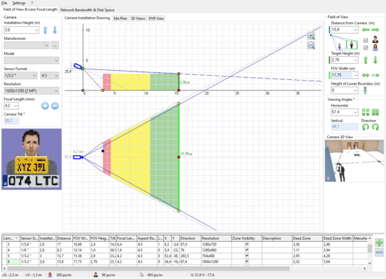
First tab - "Camera Installation Drawing". This tab allows you to estimate FOV, angles, lens focal length, set camera parameters or choose a model from the camera database.
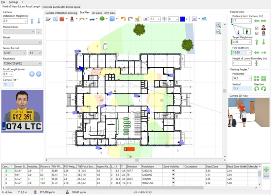
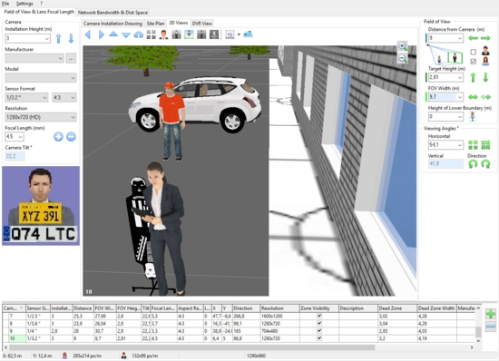
Third tab - Utilizing the tab "3D views" In the “Site Tab” view, choose a camera by clicking your mouse cursor directly on it. Switch then to the “3D view” tab. You will see an enlarged 3D view from each camera. This view is based on the camera mounting placement found when the "Site plan" tab is active. One can also mouse click/select a camera number on the lower “Camera list” to bring up the 3D views of additional cameras.
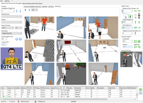
Fourth tab: On the tab "DVR View" you can produce a representation of views of cameras as a security guard would monitor them.
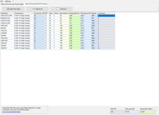
Fifth tab: On the tab "Network Bandwidth & Disk Space" you can estimate required disk storage space to store video archives and calculate required network bandwidth for network cameras.